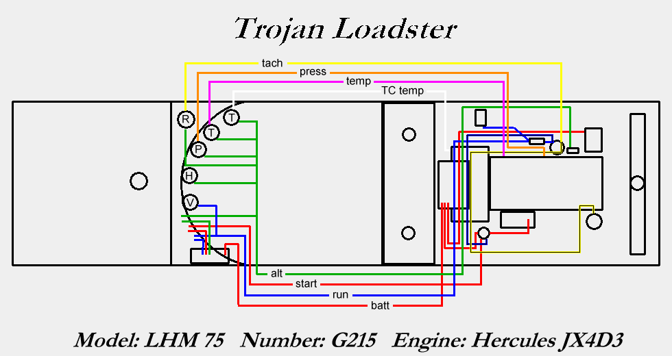
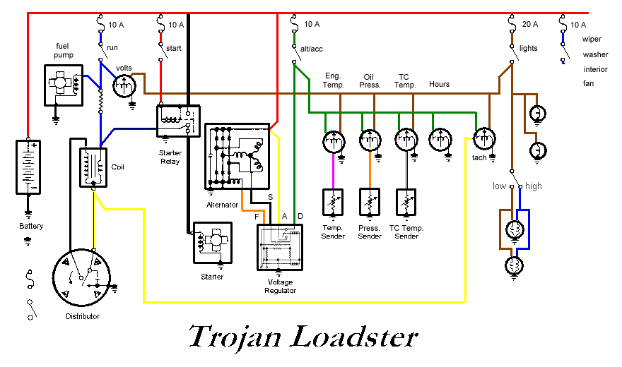
I have completely rewired this loader (which was already updated to a twelve volt system - alternator, starter, coil, etc.). It also already had an electric fuel pump. (see the schematic diagrams below) I installed a fuse box made from a six inch or so square waterproof plastic workbox I found once upon a time at the dump, in which I put an eight circuit AGC fuse style fuse block I used to have in my Ford truck for auxiliary circuits. I used 12 ga wire for the main circuits, and 18 ga for the gauge signal lines and lighting. I had an old Audi 5000 Battery wire, with two eight or so gauge red wires factory installed to the battery post clamp, so I used it to run to the starter relay, the alternator and the fuse box. I used a homemade 2.7 ohm ballast resistor (to match the coil primary resistance). I don't think there was one in the circuit before (or a resistive wire), and the coil said on it "12 volts, must use external resistor," so I think I know why the points were getting nasty and making it hard to start and keep running at times. I am using the fourth terminal on the starter relay (blue striped wire) to bypass the ballast during cranking for maximum spark. The gauges are used units, along with their senders where applicable, that I had stashed from my 1980's Audis. The hour meter is new, and I have not bothered to install a tachometer yet. It would be nice to find a 4000 rpm unit that fits the small (2 1/8") bezel hole. I removed the key switch and replaced it with two "on" switches and a push-button "start" switch (actually an add-on horn button I had lying around). The first "on" switch only energizes the coil, fuel pump, and voltage meter (which replaces the old, working [!] ammeter), for minimal load starting, and the second one powers the alternator field wiring and the other gauges.  The wiring runs through three main split loom "busses" - one down the left side for running power circuits, one down the right for various gauge signals, and one from left to right over the torque converter to get some of the running circuits from one side to the other. I haven't wired the lights yet (except for gauge illumination), but they will be installed at each corner of the cab, aimed fore and aft, and will run off one hot wire daisy chained between them. These will be grounded, as are most of the devices on board, to the chassis at their mounting point. Here are a couple of bits of angle iron I welded on to "protect" the looms as they head rearward through the passenger compartment:   Here you can see some of the new wiring as it connects to the starter relay:  One of these days I will add a picture of the right, "accessory", side of the motor, showing the looms and wires and various terminations. Whenever I think it looks nice enough! Here are my schematic diagrams. The first corresponds roughly to the physical layout of the wiring, and was used partly to help me organize the looms and make sure the wires were long enough. The second is a "true" schematic, which simply shows the electrical relationships between all the system components. |

